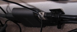
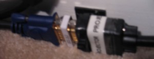
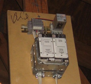
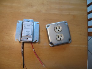
Prepared the INSTEON controls and PJ outlet for the attic. Also mounted the relay board up in the attic and wired it all up. Sconces are wired into this as well, programmed them so they ramp up/down. Made a macro on my USB programmable INSTEON controller so whenever the screen goes up the Sconces ramp on, and when the screen goes down they ramp off.
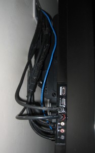
TV is all wired up and center channel & sub RCA cabling is done. TV wires look all gummy because the cheap electrical tape that wrapped around the plastic protecting all the connectors and binding the cables together left all the adhesive behind…and I pulled it off early so some insulation came in contact with it. Will clean it up later on.
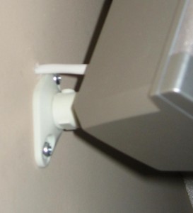
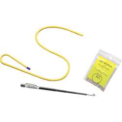
Clean speaker wire installs all done. The mounts I used for the speakers suck–cheap plastic junk, no covers for the screws, ugly as hell… The cool part is I used a very handy tool from LSD (Labor Saving Devices) called a “Wet Noodle” it’s a flexible bit of thin stiff tubing with a magnet on each end. It comes with some ball chain attached to a split ring. The way it works is from the attic you drill a hole through the top plate of the wall frame and drop the ball chain in the hole (split ring prevents the end from falling into the hole) and then drill a hole in the wall where you want to bring the wire out, and you retrieve it using by inserting the Wet Noodle and catching the ball chain on the magnetic tip affix your wire or poly and go back in the attic and pull the ball chain out and you got your wire through. I was able to drill holes just a bit bigger then the gauge of the speaker wire and pull the speaker wire through using this tool/technique. Well worth the 22 bucks, will definitely come in handy again.
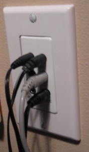
IR connecting block installed and IR Receiver too. Receiver went in the vaulted ceiling area since the screen being down would block it’s placement elsewhere. Doing this again I wouldn’t use an inwall connecting block, it just added more wires traveling from the wall to the media cabinet, had I used the non-in wall version I would simply have a Cat5 cable coming across and that would be it. This way I have 3 emitter cables traveling across, along with a power cable.
Wired in the HDMI and Component splitters to get output for both TV and PJ. Super Cheap HDMI splitter, so far no issues. Component picture really suffers on the PJ pretty sure I need to get a better VGA to component cable.
